In a previous post we have identified the need to have a translator from the UML language, which is used to capture requests from customers, to the programming languages used by software developers to make computers fulfill those requests.
The good news is that several products have been developed and are currently available to perform that task. Every tool that offers the possibility of “round-trip engineering” is a candidate. The scope of this post is to show how a specific tool implements it and how we can take advantage of what is available.
Prerequisites are a basic knowledge of
- the object-oriented paradigm
- the UML language
- the constructs of the C++ implementing the object-oriented paradigm. I am using C++ because of my experience and also because it is the language that, at least in my opinion, presents more challenges than others in this field. However, We’ll be focusing on an embedded environment in this example and for this reason we’ll be using C++ syntax, but not the C++ Standard Library. There are reasons, both technical and commercial, for not using the STL in embedded environments, but this might be a subject for a different post.
- the User Interface in Microsoft Visual Studio
Several good resources on those subjects can be found online.
The presentation of the subject here is going to be generically applicable in different environments. However, in order to be able to present some practical examples, I am going to use
- Sparx Systems Enterprise Architect rel. 13.5, Professional Version, as a UML modeling tool. At the time of writing, a 30-day trial version can be downloaded from here.
- LieberLieber Embedded Engineer rel. 2.1, an add-in for Enterprise Architect that improves the capabilities for code generation from a model. At the time of writing, a 90-day trial version can be downloaded from here
- Microsoft Visual Studio 2017, Community Edition. Disclaimer: only sofware covered by Open Source licenses is going to be used here and for this reason I can use the indicated version of the development environment. The business environment of the readers can be different and I can’t give advice about the suitability of any licensing in their case. Please check before using the tool) The different versions of the development environment are available here .
- Microsoft Windows 10 operating system.
1. Environment Setup
- Install a version of Microsoft Visual Studio 2017 suitable for your business environment. In my environment I can use the Community Edition and I optimize it for the C++ language.
- Install Enterprise Architect rel. 13.5. Default installation was good enough for me.
- Install Embedded Engineer rel 2.1. Default installation was good enough for me.
There are some add-ins to facilitate the interaction among the different tools, but I won’t make use of them in this post.
2. Visual Studio Project Setup
- Create a Microsoft Visual Studio empty project called MDDTest. I am not going into details on this. In my environment it can be done by selecting File -> New -> Project -> open Installed (on the left side) -> select Visual C++ -> select General.
In the center of the page a template for the “Empty Project” should be available. Just highlight it. - Give the name MDDTest in the textbox close to Name (the Solution Name field is automatically updated)
- Give the place for the location of the project on your workstation in the Location field and click on OK. You should end up with something like in Fig. 1

Fig. 1 – Initial setup for the Visual Studio project
3. Enterprise Architect Project Setup
- Create a New project in Enterprise Architect.
EA menu (left to the Start menu) -> New Project… -> select a folder where to store the model -> Enter MDDTest as the project name. - A “Model Wizard” window opens. This is about the selection of model patterns to be used in a project, but for this project we won’t need any; therefore, just click on OK. You should end up with something like in Fig. 2.
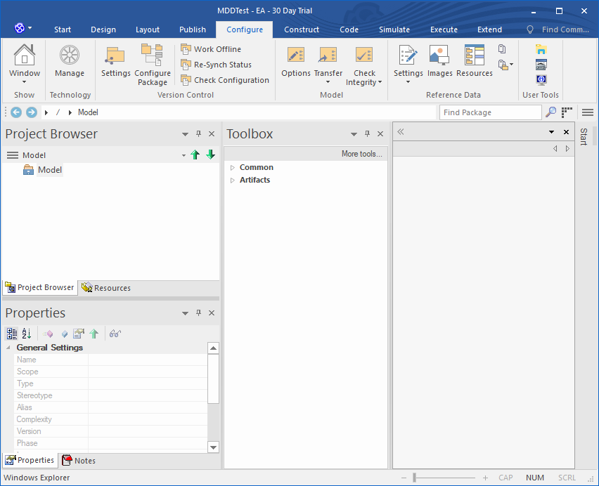
Fig. 2 – Initial setup for the Enterprise Architect project
- Please note the Toolbox pane. If not present it can be visualized by selecting Design -> Diagram -> Toolbox.
4. General Configuration for the Project on Enterprise Architecture
- Set the default code generation language to C++
Configure -> Options -> Source Code Engineering -> select LL Embedded C++ from the list close to “Default Language for Code Generation“ - Create a view in the project.
We just create a container for our diagrams and entities. The structure of the project is not important for this tutorial. In the Project Browser
Context Menu on the project name -> Add -> Add View -> enter MDDTest as a name -> check Class View -> click OK. The view is created under the Model in the Project Browser (the tree may need to be open) - Create a package in the view. This is going to be the container for the classes created in the project.
Context Menu on the view just created -> Add Package… -> enter MDDTest as a name -> click OK (other default values are fine) -> click OK on the Model Wizard window. - Create a class diagram in the view.
Context Menu on the package just created -> Add Diagram -> name is prefilled -> for Type select UML Structural -> and Class as a Diagram Type -> click OK. A new class diagram is created.
5. Considerations Before the Real Work Begins
With the environment now set up, we can start modeling our system. In our case this would be a very simple class offering a logging service. Despite its simplicity the process of modeling it will offer the possibility to highlight many of the practical issues faced by developers when modeling in an MDD environment.
As the name suggests, the development starts from the model and the idea is that the source code of our system should be generated from it.
The simple idea behind all this is that whatever we generate from the model should compile successfully in Visual Studio without any further intervention.
Over the years I have had the strong impression that MDD didn’t achieve the success it deserves because of the little effort that is needed by developers at this stage. In the next paragraphs you’ll notice that sometimes modeling with the aim of generating code can be a bit frustrating at first because we need to master the mapping between what our tools (EA and Embedded Engineer in our case) will generate and the compiler in Visual Studio.
Things like how can we make a <<use>> dependency in UML generate the right #include in C++ might be seen as a waste of time, because we can always go in Visual Studio and add the right thing at the right place in almost no time at all. However, we should not forget that in doing so we would start to lose the direct link between what has been discussed with the customer and the actual implementation, a pattern too often seen in unsuccessful projects.
I have been honored to work with customers that would impose in the contracts the type of MDD discussed here (and check themselves that we did developed software that way!)
On the other hand, once we discover how to do it, it can be easily seen that not a lot is needed in the everyday work for developers. This simple tutorial probably covers already the best part of the ‘problematic’ issues that arise in MDD.
6. The Toolbox
We’ll be using it a lot, so a short introduction might be useful.
The panel has a button spanning the whole width and labeled “More tools…“. Clicking on that we have access to a list of names of technologies for which the corresponding UML tools will be made available for modeling.
Just as a check, if you see in the list the LieberLieber Embedded Engineer element in the list (you may need to scroll down the list), the add-in has been installed properly. We are going to use this element, so you can select it already. This will make appear the entities specifically handled by the tool. For each entity there is an icon and a label. If the labels are not visible, a Context Menu on any of them will show the “Show Labels” option.
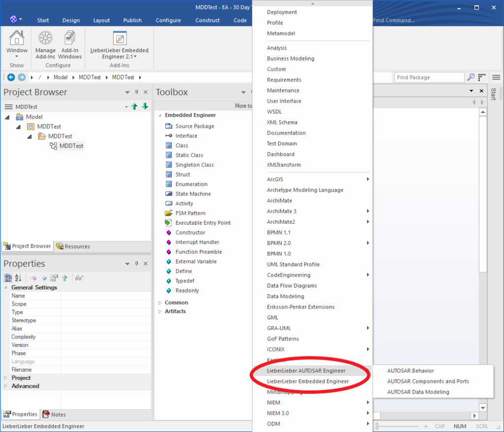
Fig. 3 – Toolbox with options for Embedded Engineer
7. Modeling the System
7.1 Model a Class
The system will contain a single class, called Logger. The class will be responsible for writing on the console logging messages from applications using this library. The implementation of the class won’t deal even with the minimal safety checks, at least at this early stage, so it is very likely that the output of the tutorial will fail any decent unit test case written against the class, but I hope that it is clear by now that this is not the point here. This class should only be used in this tutorial. I accept no responsibility for using it either directly or in a derivative work in any different environment.
- Pick the Class icon and drag it into the diagram. A window immediately opens, with a title “Class:Class1“.
- Let’s change the name Class1 to Logger in the text box and add some description in the field below, like “Logger class with filtering messsages capabilities“. This description is going to be shown in the generated code, one of the great benefits of MDD.
- On the right panel of the window locate the label “Language” and select the “LL Embedded C++” element in the listbox next to that label, if not already shown.
- click Apply -> click OK. This is the window where we might need to change some properties later, at class level, to generate C++ code that Visual Studio can compile. We can always go back to it from Context Menu on the item (either in the class diagram or in the Project Browser) -> Properties…
7.2 Add an Enumeration
Let’s assume that it has been decided that the current level of logging requested by customer applications can have only two values, say, TRACE and ERROR. We notice that we can put an enumeration of values in the model (you’ve guessed it, it is going to be “translated” in an enumeration in C++ once we generate the code!)
- Pick the Enumeration icon and drag it into the diagram. A window immediately opens, with a title “Enumeration:Enumeration1“.
- Let’s change the name Enumeration1 to LogLevel in the text box and add some description in the field below, like “This enumeration defines the filters allowed by the logger library“.
- On the right panel of the window locate the label “Language” and select the “LL Embedded C++” element in the listbox next to that label, if not already shown.
- click Apply -> click OK.
Now we want to enter the the actual values of the enumeration.
- Context Menu on the enumeration just created -> Featured & Properties… -> Attributes
- Enter LOG_TRACE as the name of the first new attribute, with 0 as its initial value
- Enter LOG_ERROR as the name of the first new attribute, with 1 as its initial value
- Click Close. We don’t need anything else from this menu. The two values should now be shown in the diagram.
7.4 First Test
Before completing the modeling of the system we can already check if we are doing well. We are going to generate the C++ code from what we have done so far and see what Visual Studiio thinks about it. Again, this is the reason for using MDD and in the real world we’ll find ourselves doing this kind of checks very often.
- Code generation. There are several options to generate code in EA and Embedded Engineer. We are going to use the generation of a whole package. In the Project Browser -> Context Menu -> Extension -> LieberLieber Embedded Engineer 2.1 -> Generate C++ Code. There is also an option from Enterprise Architect but it is not optimized for C++.
- The first time we are requested to select the folder where to generate the files, unless we have defined a default folder in Embedded Engineer. Of course, we want to put them in a place where we can easily associate them to Visual Studio. If you have a standard project in VS, a good place would be in the folder MDDTest\MDDTest.
- Three files should be generated LogLevel.h, Logger.h, Logger.cpp .
- Switch to Visual Studio and open the MDDTest project if it isn’t already. In the Solution Explorer panel highlight the project name (not the solution), then select Project -> Properties -> Configuration properties -> General. On the right pane of the window search for Project Default -> Configuration Type and select Static Library (.lib) for this project, because this is what we are going to create.
- Add the header (.h) files generated top the Header Files folder in Solution Explorer and the implementation file (.cpp) in the Source Files folder.
- The build of the solution (F7 or Build -> Build Solution) should be successful. If it is, we are on the right way. If it isn’t, the compiler will tell us and we might need to tweak something, but in the model, of course.
It continues in Model Driven Development: The Basics (Part II)
Notice on copyright holders
Visual Studio is a registered mark of Microsoft Corp., USA. Enterprise Architect is a registered mark of SparxSystems Ltd., Australia. Embedded Engineer is a registered mark of LieberLieber Software GmbH, Austria

This work is licensed under a Creative Commons Attribution-NonCommercial-NoDerivatives 4.0 International License.