This is the first post of a short series about model driven engineering using State Machines.
Here we are going to prepare the development environment for the next steps. Since modeling using state machines is particularly suitable for embedded environments, we are going to use the indicated (inexpensive) board from Microchip.
Legacy Code: How To Reverse-Engineer
1. Introduction
In a previous post I came to the conclusion that reverse-engineering might be needed the most by new team members working in an already established project.
This covers the scenario when knowledge is not widespread and there is little time to get “the full picture” of what’s going on before being asked to be a contributive member of the team.
The only possibility is to go through the code and try to understand what the team has come up with over the lifetime of the project. Of course, experienced and /or talented programmers could be able read and understand the code fast, but they would still need to rebuild all the discussions with the customers, if they want to understand what the system is supposed to do. For the latter, some diagrams can definitely help.
In principle, reverse-engineering should be used to bring source code into a Model Driven Development process and, for this reason, it should be necessary only once. However, I have seen the process applied either just once to create some diagrams and produce some kind of documentation, or by having someone doing it regularly from the source code, just to maintain the diagrams in sync with the code. I normally call the output of the latter case UML “pictures” or “paintings“and not “diagrams“, because they are not used to communicate among stakeholders before or during development, but probably only for some contractual clause.
Instead, I’ll identify some clear objectives that, depending on the size of the project, can be achieved relatively quickly. We are going to use our tools
- to identify all the entities defined in the source code to implement the system
- to model the most important relations between the defined entities.
Legacy Code: How Can Model Driven Development Help?
This post tries to summarize my professional experience with legacy code and define the scope where MDD can help with it.
In recent years there has been a debate about how to define legacy code. I am probably not qualified to attempt any formal definition, but I am going to give one that corresponds to my experience.
Legacy code is that type of source code you are required to work with when you join a team of an already long-running project and you, like most of the team, don’t have a clue, not only about what the code does, but also about what the software is supposed to do. In a high percentage of cases you are immediately told by senior team members that the documentation is out-of-date, if available at all.
Very soon, new requirements, or, worse, “bugs” to deal with start to arrive.
Should they come either from a newly agreed set of requirements, or a formal test procedure, or from a phone call of an angry customer, the situation is the same, the new member is hardly in the position to deal with the requests with the necessary confidence. Add to that the pressure from the Project Manager that sees a red bar about bugs growing up in some spreadsheet and the life of the new member may become immediately very miserable indeed.
I am sure many of us have been there and you know what I mean.
Luckily, Model Driven Development can help in these situations. It’s not a panacea, also because it can have different levels of acceptance in different teams, but it’s the process that I have used every time as soon as I am given access to the source-control system of a project, with a very satisfying success rate.
Model Driven Development: The Basics (Part II)
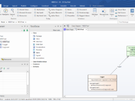
In Model Driven Development: The Basics (Part I) we have set up an environment for modeling a system with Enterprise Architect and for generating C++ code to be compilable in Visual Studio.
In this second part of the post we are going to build on that and see how some fundamental entitites in UML are translated into C++. This should give the readers enough experience to play with the basics of MDD and be able to find more advanced features themselves. For brevity I am not going to describe in detail how to access features which have already been described in Part I.
1. Add an Attribute to the Logger Class
The objective of this activity is to put in the Logger class an element which records the current required level of tracing. As usual, we want to use UML while keeping in mind that we want the tools to generate valid C++ source code from that.
Model Driven Development: The Basics (Part I)
In a previous post we have identified the need to have a translator from the UML language, which is used to capture requests from customers, to the programming languages used by software developers to make computers fulfill those requests.
The good news is that several products have been developed and are currently available to perform that task. Every tool that offers the possibility of “round-trip engineering” is a candidate. The scope of this post is to show how a specific tool implements it and how we can take advantage of what is available.
Prerequisites are a basic knowledge of
- the object-oriented paradigm
- the UML language
- the constructs of the C++ implementing the object-oriented paradigm. I am using C++ because of my experience and also because it is the language that, at least in my opinion, presents more challenges than others in this field. However, We’ll be focusing on an embedded environment in this example and for this reason we’ll be using C++ syntax, but not the C++ Standard Library. There are reasons, both technical and commercial, for not using the STL in embedded environments, but this might be a subject for a different post.
- the User Interface in Microsoft Visual Studio
Several good resources on those subjects can be found online.
The presentation of the subject here is going to be generically applicable in different environments. However, in order to be able to present some practical examples, I am going to use
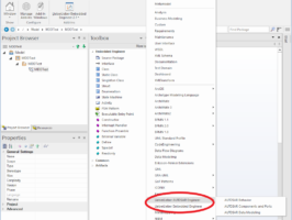
- Sparx Systems Enterprise Architect rel. 13.5, Professional Version, as a UML modeling tool. At the time of writing, a 30-day trial version can be downloaded from here.
- LieberLieber Embedded Engineer rel. 2.1, an add-in for Enterprise Architect that improves the capabilities for code generation from a model. At the time of writing, a 90-day trial version can be downloaded from here
- Microsoft Visual Studio 2017, Community Edition. Disclaimer: only sofware covered by Open Source licenses is going to be used here and for this reason I can use the indicated version of the development environment. The business environment of the readers can be different and I can’t give advice about the suitability of any licensing in their case. Please check before using the tool) The different versions of the development environment are available here .
- Microsoft Windows 10 operating system.